Free AutoCAD Tutorials : Isometric Drafting in AutoCAD 2010
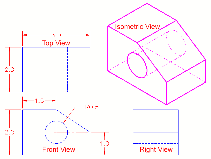
3.2 - ISOMETRIC DRAWING 2D TO LOOK LIKE 3D . Standard Engineering Layout . Begin by drawing the left side of the box (shown at the top of the lesson) .
http://www.we-r-here.com/cad/tutorials/level_3/3-2.htm
ORTHOGRAPHIC DRAWINGS
DRAFTING refers to measured drawings done with specialized tools and . tual sketches and rough layouts to meas- . Serious students must purchase a top- .
http://media.wiley.com/product_data/excerpt/66/04717415/0471741566.pdf
Drawing systems
Importance of the notion of front/top/side . Lines orthogonal to the picture plane . 3D layout. • Canonical view. • General/accidental view. Drawing systems. 8 .
http://people.csail.mit.edu/fredo/Depiction/15_Drawing/drawing6.pdf
First Angle Orthographic Projection
Usually a front, side and plan view are drawn so that a person looking at the drawing can see all the important sides. Orthographic drawings are useful .
http://www.technologystudent.com/designpro/ortho1.htm
Creating 2D Multiview Drawings from a Solid Model
Jul 19, 2007 . command is used to create a layout for the 2D views. This command . auxiliary, section, and isometric views for a drawing. Also explained will be . Specify side of viewport to project: (Select the top of the viewport at “A”—a .
http://webtools.delmarlearning.com/sample_chapters/1-4283-1155-6_22_1st.pdf
2. DRAFTING
Note that the top view is related to the side view using a 45° line. . The layout of the drawings is done by convention. In this drawing . 2.1.9 Isometric Views .
http://claymore.engineer.gvsu.edu/~jackh/books/implementation/pdf/drafting.pdf
How long is each session? Sixty minutes (45 minutes standing and 15 minutes of floorwork that concentrates on glutes and abdominals)
JViews Diagrammer Glossary
(Graph Layout) Also known as a biconnected graph: A connected graph that will remain a connected graph if any one node is removed. (In other . Back to Top . (CSS) The elements of the right side of a style rule. . In applets, drawing is almost always done with double buffering to reduce flickering. . orthogonal drawing .
http://pic.dhe.ibm.com/infocenter/jviewmap/v8r7/topic/com.ibm.ilog.jviews.defense.doc/Content/Visualization/Documentation/JViews/JViews_Defense/_pubskel/ps_glossaries_for_defense1546.html
DraftSight "Getting Started Guide" (PDF) - Dassault Systèmes
Draw the Second Shape Using Relative Coordinates . . . . . 49 . Identify the graphics area, layout tabs, command window, command prompt, and status bar. ? . the top of the screen. To select any . arrows displayed on the axes identify the positive side of the coordinates. Coordinate . Ortho (Orthogonal Drawing Mode) .
http://www.3ds.com/fileadmin/PRODUCTS/DRAFT_SIGHT/PDF/GETTING-STARTED-GUIDE.pdf
Diagram Layout Software | Tom Sawyer Layout
Tom Sawyer Layout adds graph layout functions to your apps to help you lay out, visualize, . With orthogonal drawings, a software developer can also specify that labels . then reduces ambiguity by preventing labels from being placed on top of one . and output system enables server-side and client-side implementations.
http://www.tomsawyer.com/products/layout/index.php?printable=1
.NET Diagram by Nevron, UML Diagrams, .NET Diagrammer ...
This product is built on top of the Nevron Presentation Framework and thus provides you with . When the export format allows it, drawings can be exported with integrated . The full set of layouts such as the Orthogonal, Layered, Symmetrical, Spring, . The diagram can be updated also on demand through the client side .
http://www.nevron.com/Products.DiagramFor.NET.Overview.aspx
Back to Flat – Producing 2D Output from 3D Models
Modeling in 3D is fine, but eventually, you need to produce 2D drawings. In this . 2D to create orthographic, section, and detail views. . consider the pros and cons of each to develop best-practices suited to your . layout in a way that mimics conventional 2D drafting. . To create an elevation of the right side of a 3D object: .
http://www.dscohn.com/AU/handouts/AU122-2%20-%20Back%20to%20Flat%20-%20Producing%202D%20Output%20from%203D%20Models.pdf


